|
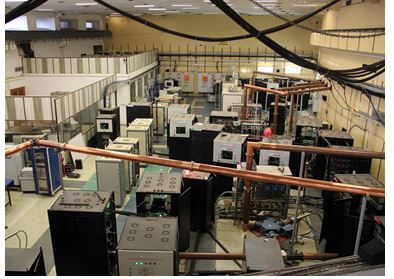
RF System for 2.5GeV,200mA Synchrotron Radiation Source Indus-2 is developed. The role of RF System is to boost the electron energy from 600 MeV to 2.5 GeV and compensates the SR losses by the circulating particles in the bending magnets and insertion devices. The system is designed to generate an accelerating voltage more than 1750 kV at 505.812 MHz which gives sufficiently high quantum and Touschek lifetime. The RF system employs six elliptical cavities, four are powered by solid state, one by Klystron and sixth cavity by IOT based RF amplifier. One RF station consists of interlock unit, digital LLRF (DLLRF), high power RF amplifier with power supply, transmission line system and RF cavity. RF transmission system was realized using 61/8” EIA coaxial lines and coaxial line components operating at normal atmosphere pressure having max. VSWR of 1.07 and insertion loss less than 0.4dB.
a) Klystron RF Amplifier
The Klystron RF amplifier is based on 60 kW multi-beam, integral-cavity klystron KY400, with dispenser type of cathode. The klystron is biased using -20 kV, 5.5 Amp HVDC power, the auxiliary power supplies for its filament, ion pump and mod-anode are floating at beam supply voltage of 20 kV. The current and voltage signals floating at beam voltage are monitored by an optical fibre interface. To cater to the wide varying input conditions and to meet the high voltage requirements of possible loads, these power supplies were controlled through six SCRs in 3-Φ AC regulator scheme. Having either Delta connected primary or Star connected primary without neutral, of the main transformer, avoiding 3rd harmonics in the line. A three-phase linear inductor is intentionally kept at the primary side of each power supply unit to reduce the fault current level, to limit the higher order harmonics and to limit the worst-case di/dt subjected to semiconductor devices employed in these power supplies. Various protection circuits like over voltage circuit, over current circuit, shunt trip from klystron, phase failure/reversal circuit, spark and arc control circuit, transformer oil top and bottom float (level), SCR temperature high, oil temperature high etc are also incorporated. In this supply a harmonic line filter is employed to keep the input power factor near unity and also to keep the line harmonics within the limit specified by IEEE Std-519, 1992. The filter components are intentionally tuned to 228 Hz, to avoid parallel resonance with the source. Crowbar protection is provided to Klystron, which operates within few microseconds in case of any arcing; the energy dissipated in the klystron is limited below 20 Joules.
|
|
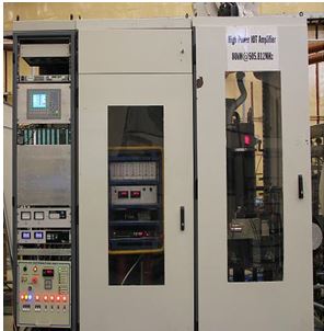
Fig. 3 : 60kW multi-beam, integral-cavity 505.8 MHz klystron and its power supply |
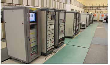
b) IOT based RF power System of Indus-2
As an alternate to phased out 60kW, 505.8MHz klystron, 60kW CW E2Vmake IOTD2130 based RF power amplifier was developed at 505.8MHz and deployed in Indus-2 RF system to feed one out of six RF cavities. In configuration, the RF amplifier system consists of 60kW IOT based Final Power Amplifier (FPA), 300W solid-state driver-amplifier stage and a 10W wide band pre-driver amplifier stage connected in cascade, providing over all power gain of 77dB with efficiency more than 60% and P1dB bandwidth of 2MHz along with harmonic and non-harmonic spurious less than -36dBc and -50dBc respectively. Various constituent sub-systems of the IOT amplifier- PLC based sequencing, control, monitoring & interlocking system, CPLD based fast RF interlock system, -36kV/3A HV beam supply, 7V/25A solenoid supply, auxiliary DC power supplies, water and air cooling system, driver RF amplifier are realized and integrated with IOT amplifier. A CPLD based RF interlocks are implemented for fast tripping of RF within 100µs so as to protect high power IOT from RF malfunction due to RF input over drive, excessive load VSWR at IOT output port, IOT internal arc, circulator arc etc that may exist during its operation with high Q RF accelerating cavity. Crowbarless IOT beam power supply of -36kV/3A, composed of six numbers of parallel connected -36kVDC/0.5A modules configured in master salve configuration, has stability better than 0.5% and stored energy less than 20 joules, providing required DC beam power to the density modulated bunched electron beam of IOT between cathode and anode. The auxiliary DC power supplies of -7V/25A filament supply, 4.5kV/10mA Ion-pump supply and -200V/100mA control grid supply, along with their voltage and current monitoring units are assembled on a isolated 50kV HV deck and interfaced to PLC system by means of optical fiber interface for implementing control, sequencing, monitoring and interlocking logic with required HV isolation. RF power from IOT output port is transmitted to Indus-2 RF cavity by means of 6-1/8” rigid coaxial line system consisting of 6-1/8” 50dB directional coupler, 100kW RF dummy load, rigid line sections and bends, flexible line section, developed in house. Performance parameters of the IOT power system are shown in table below.
Table 1: Main performance parameters of IOT RF@505.8MHz
| Sr.No |
Performance Parameter |
Value |
| 1.0 |
Max. RF Power output |
60kW CW |
| 2.0 |
Power gain |
22.5 dB |
| 3.1 |
Operating frequency |
505.8 MHz |
| 3.2 |
1-dB Bandwidth |
2.0 MHz |
| 4.1 |
Harmonic distortion |
<-36 dBc |
| 4.2 |
Non Harmonic spurious output |
<-50dBc |
| 5.0 |
Efficiency |
≈60% |
|
|
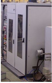
Fig. 4 : IOT amplifier as set-up in Indus-2 |
Fig. 5 : IOT amplifier connected to system |
c) Solid State RF Amplifiers for Indus-2 SRS
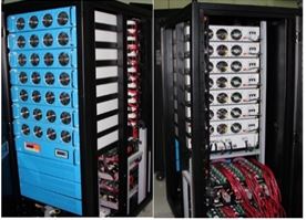
RRCAT has designed and developed four nos. of 505.8 MHz Solid State Amplifiers of 60 kW each providing total RF output power of 240 kW. All these four amplifiers have been successfully deployed and commissioned in Indus-2 Synchrotron Radiation Source in phased manner. Starting from design, modular and scalable, developed solid-state amplifiers are housed in customised cabinets and employs multiple 500W RF amplifier modules, power dividers, radial power combiners, phase shifter and high power directional coupler. All these indigenously developed components, were tested and integrated with safety interlocks, FPGA based data acquisition system and water cooling circuit to make a complete high power amplifier system delivering RF feed to RF cavity.
|
Fig. 6: Indus-2 RF gallery showing 10 kW racks of solid state RF amplifiers |
d) 50 V, 700 A DC power supply for solid state RF amplifier
A 50 V, 700 A voltage regulated modular hot swappable DC power supply has been designed and indigenously developed to bias 500 W, 505.8 MHz solid state RF amplifiers in Indus-2. This power supply achieves output voltage stability ≤ 0.2 %, output voltage ripple (pk-pk) ≤0.2%, efficiency ≥ 90 %, input power factor ≥ 0.98.
Total 08 units of 50 V, 700 A DC power supplies are deployed to bias solid state RF amplifiers of Indus-2.
|
Fig. 7 : 50 V, 700 A DC power supply |
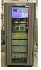
e) Digital Low level RF Control for Indus-2
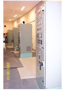
LLRF control system is installed in each RF station to keep amplitude and phase of RF field stable in the accelerating RF cavity, initially LLRF system of Indus-2 was based on analogue technology. To have inherent advantages of digital system like flexibility, adaptability, good repeatability and reduced long time drift errors as compared to analogue system digital LLRF (DLLRF) systems have been developed and commissioned for all six RF stations. This development involves use of latest technologies of Digital Signal Processing, RF signal Processing and Fast Feedback Control Systems based on FPGAs. RF signal processing unit is developed for down conversion, synchronized clock generation and amplitude & phase control of RF signal. Digital feedback controller is realized using FPGA with suitable codes prepared in VHDL and LabVIEW. A Real time RF cavity simulator is developed to test and optimized the DLLRF system in Lab. DLLRF systems systems provide 20 dB dynamic range and 360° phase correction with amplitude and phase stability of 0.5% and 0.5° respectively. PLC based RF cavity Frequency tuning and power monitoring system has been upgraded one station. In each RF station the interlock unit safeguards precious RF components and provides human safety. FPGA based compact Digital LLRF system has been designed and developed in a single 32U rack that caters the requirement of station 5 and 6 simultaneously. This rack consists of two RF processing unit of 3U height. In a single PXIe chassis two FPGA card each having two high speed ADC and DACs are used for digital algorithm implementation. A common GUI has been created in LabVIEW that provides control and monitoring of important parameters for both stations and serves as local panel for Digital LLRF system
|
|
Fig. 8 : Digital LLRF control System in Indus-2, with a view of single DLLRF rack |
|