Indus-1 Beam Diagnostic Systems
1. Beam Profile Monitor (BPM)
BPMs are interceptive diagnostic devices developed for the observation of transverse profile of electron beam. They
provide a visual observation of beam spot size and shape. They serve as a very useful guide to the operator in
steering the beam in the transfer lines and first turn revolution of injected beam in the booster and storage ring.
BPMs work on the physical phenomenon of fluorescence effect. A UHV Compatible rotary motion feedthrough is used
to move a screen of 1 mm thick fluorescent ceramic (AF995R) into an interceptive position in the beam chamber. The
beam strikes the screen and produces a glow of fluorescent light. A UHV compatible glass observation window is
provided to view the fluorescent spot with a video imaging system. A number of BPMs have been installed in the
Indus-1 accelerator system consisting of Transfer Line-1 (TL-1), Booster Synchrotron, Transfer Line-2 (TL-2) and
Indus-1. It is possible for the operator to select any one BPM and view the beam spot on the video monitor installed in
the control room. Beam spot can be captured with the help a softwrae developed in-house for later analysis.
In recent past four numbers of upgraded BPMs with improved features have been designed, developed
and installed in new TL-1. Further, in place of old BPMs of TL-2, four numbers of upgraded BPMs have
also been installed.
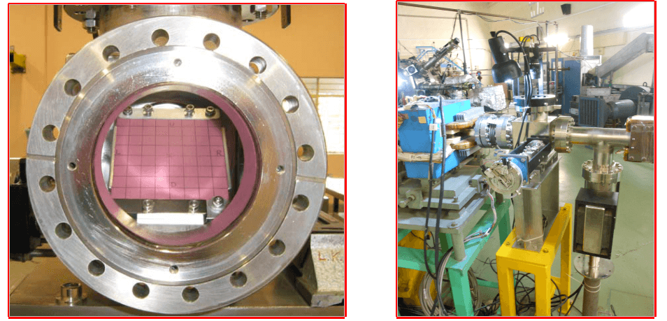
Figure 1(a):Fluorescent ceramic (AF995R) assembled Figure 1(b)TL-1 Beam Profile Monitor
2. Beam Slit Monitor (BSM) :
beam slit monitor (BSM) is a multifunction diagnostic device. While it can be used as a slit with adjustable
aperture to define the beam (similar to a beam scraper), it can also be used to determine the horizontal and vertical
beam profile by measuring the current captured by the slit blade as it scans the beam in transverse direction. A
fluorescent screen (Cr doped alumina) is mounted on each blade of the slit. This enables it also to act like a
conventional fluorescent screen for visually observing the beam profile by stopping the beam on one blade. As an
adjustable “Hole” monitor, it allows a portion of the beam to pass through, while one can view the beam edges falling
on the blades.
The device has four independent blades, two blades moving in opposing horizontal direction and the remaining two moving in vertical directions. Vertical blades have a linear stroke of 60 mm, and horizontal blades 40 mm. This arrangement allows for positioning of the hole (and slit) in a field of 60 mm x 40 mm around the theoretical beam centre line. All the parts near the beam line are made of vacuum compatible, non-magnetic materials. The device operates under a vacuum of 10-7 mbar. The movement mechanism has a guiding arrangement to precisely maintain the orientation of the blades. It also has an anti-collision arrangement for the blades. The operation is done remotely. This device has been developed with inter-group collaboration in RRCAT.
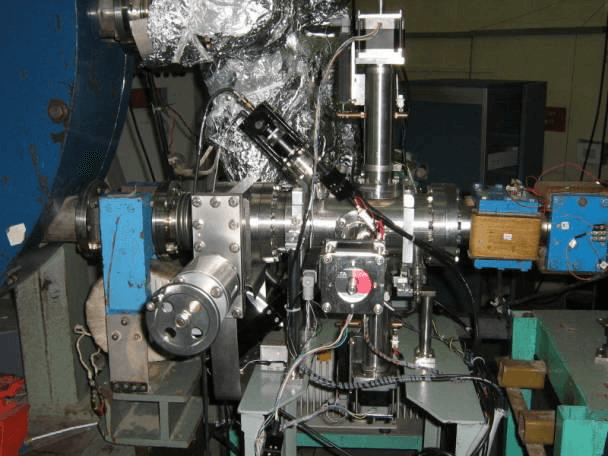
Figure 2: Beam Slit Monitor installed in TL-1
3) Image Acquisition and Analysis Software for Accelerator Applications:
An image acquisition and analysis software has been developed to capture the images of electron beam spot from diagnostic devices namely fluorescent screen beam profile monitors and beam slit monitor installed in TL-1. The software allows Indus accelerator operators to grab the images in various modes of operation like continuous mode, single shot mode or triggered continuous mode. Various facilities like optical superimposition of grid for visually finding the beam size and beam position under low light conditions, viewing the image in 3D, facility for centroid calculation have been provided in software. The software allows user to create audio video interleave (AVI) of captured images along with date time stamp and image number which is helpful to correlate the beam shape and size with other machine parameters. Accelerator operators can also create AVI online from digital oscilloscope screen shots. This feature is useful to record signals available on digital oscilloscope for later analysis. The software allows users to view horizontal and vertical beam profile and beam position. User can save the image in .bmp format either automatically or manually. Some other features in the software are the facility for inserting date and time stamp on image, acquisition of selected portion of image, white level optimization of input video signal etc. The software supports online measurement of beam centroid, beam height and beam width. The software has been installed in accelerator control room and now routinely being used by Indus accelerator operation group.
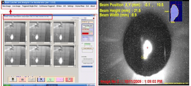
Figure 3: GUI of image acquisition, analysis software and captured beam spot on beam slit monitor
4) Fast Current Transformer (FCT):
FCTs are non-interceptive devices for on-line observation of the beam current waveform. These have been installed in TL-1 and Booster synchrotron. FCTs are designed & developed by Accelerator Magnet Technology Division (AMTD), RRCAT.
For scientific & technical details kindly contact to Shri R.S.Shinde, AMTD. (email : shinde (at) rrcat.gov.in )
5) DC Current Transformer (DCCT)
5.1) Introduction
DCCT is used for measuring electron beam current over a wide frequency range including DC. DCCT for the booster synchrotron and storage ring have been procured from M/s Bergoz, France. Their specifications are given in table-1. DCCT consists of an active current transformer and a magnetic parametric amplifier in a common feedback loop. It is based on the principle of generation of second harmonic component of the modulator frequency due to the presence of DC current passing through the core.
5.2) System Components
The system consists of:
1. Toroidal sensor
2. Front-end electronics box
3. Back-end power supply and control chassis
The toroidal cores of the DCCT are made out of thin ribbons of a high permeability alloy with amorphous structure. The front-end electronics box is kept near the core. It is connected to the toroidal sensor by two multicore cables equipped with 8-pin Burndy connectors. A multicore cable equipped with 12-pin Burndy connectors at each end connects the front-end electronics box to the back-end chassis, which is kept in the main control room.
5.3) Installation
The toroidal core is mounted on the vacuum chamber of the accelerator. An insulating gap is provided in the vacuum chamber to prevent the flow of dc and low frequency currents in the vacuum chamber wall passing through the core. The insulating gap is bypassed with capacitors to provide low impedance path for high frequency currents. This prevents the core from getting exposed to high frequency EM field of the beam and resulting heating of the core. Magnetic shielding is provided to protect the core from stray magnetic fields.
5.4) Specifications
| Parameter | Booster synchrotron DCCT | Storage ring DCCT |
| Current measurement range: |
| Range A | ± 100 mA | ± 500 mA
|
| Range B | ± 10 mA | ± 50 mA
|
| Resolution (1s integration) | < 5 μA rms | < 5 μA rms
|
| Linearity error | < ± 0.01% | < ± 0.01%
|
| Small signal bandwidth | DC… 20 kHz | DC… 20 kHz |
| Output | ± 10V | ± 10V
|
| Absolute accuracy | > ± 0.1% | > ± 0.1%
|
6) Beam Position Indicator
Beam position indicator (BPI) is used to measure the position of the charge centroid of the electron beam circulating in the accelerator vacuum chamber. In Indus-1, four-button electrode beam position indicators are used. Since it is a non-interceptive type device, it can measure the beam position without disturbing it. There are six BPIs in the booster synchrotron and four BPIs in the Indus-1 storage ring. Using these beam position indicators, the position of the equilibrium beam orbit and closed orbit distortion (COD) is obtained. The overall system is known as Beam Orbit.
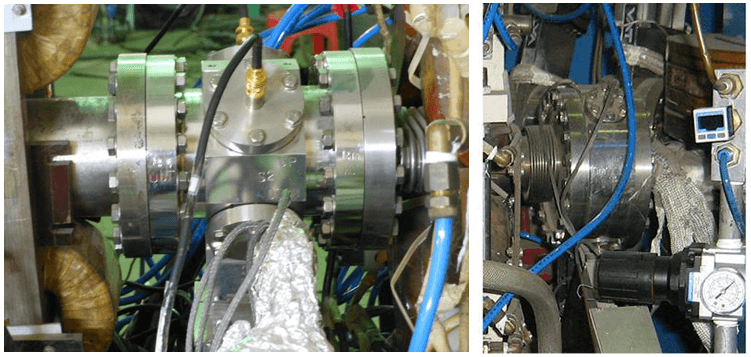
Figure 4 : Beam Position Indicator of Booster and Indus-1
7) Wall current monitor
7.1) Introduction
Wall current monitor (WCM) is used in Transfer Line-2 and storage ring for observing the bunch signal. Operator gets the information about the number and amplitude of bunches passing through the monitor. The signal from the WCM installed at the beginning of transfer line gives information about the extracted bunches from the booster synchrotron. WCM installed in the storage ring provides information about the stored electron bunches in the ring.
7.2) Principle of operation:
The beam current flowing in the beam pipe (vacuum chamber) is accompanied by an equal "wall current" (image current) on the inner surface of the beam pipe, flowing in opposite direction. Information about the electron bunch current can therefore be obtained by measuring this wall current.
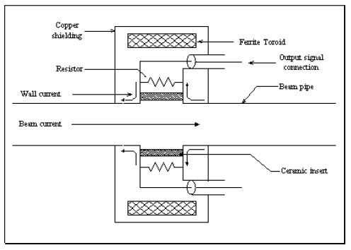
Figure 5 : Schematic diagram of wall current monitor
A schematic of wall current monitor is shown in figure 5. An electrical break is imposed in the wall current by introduction of ceramic ring in the beam pipe and this current is diverted to flow through the resistors connected across the ceramic ring. The voltage developed across the resistor due to the flow of wall current is taken out by a RG-213/U coaxial cable for further processing and observation on a digital storage oscilloscope. To avoid perturbation through circumferential modes, resistors are connected at four points symmetrically around the circumference of the beam pipe cross section. Signals from these resistors can be summed together to provide a position insensitive beam current signal. Ferrite cores surround these resistors in order to reduce part of image current flowing through the metal housing which encloses the wall current monitor. Use of ferrite core also reduces the possibility of external noise currents affecting the output of wall current monitor.
8) 2 pi -Electrode Monitor
8.1) Introduction
2pi-Electrode Monitor is installed at the end of the Transfer Line-2 for observing the bunch signal to be injected in the storage ring. Operator gets the information about the number and amplitude of bunches passing through the monitor.
8.2) Principle of operation
This monitor works on the principle of electrostatic pickup. A schematic of the monitor is shown in figure 6. It consists of a cylindrical copper electrode installed on a ceramic tube, which is a part of the transfer line-2. A ceramic insert is necessary to allow the electric field of the beam to come out and induce charge on the cylindrical electrode. The azimuthal width of the electrode is 2 pi radians due to its cylindrical shape, hence the name. As the bunch passes through the monitor, signal is induced on the electrode. A wide band buffer head mounted on the electrode picks up the bunch signal and sends it to a wide band amplifier having a voltage gain of 10. The output of the amplifier is sent to the control room through RG-213/U coaxial cable and observed on a digital storage oscilloscope.
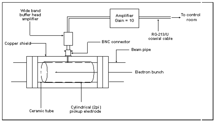
Figure 6: Schematic diagram of 2 pi-Electrode Monitor
9) Diagnostics Beamline Of Indus-1
Diagnostics beam line of Indus-1 utilizes visible light emitted from the dipole magnet to measure the beam parameters. A schematic diagram of the beamline is shown in figure 7. A mirror box is installed in the photo-physics beamline from where a part of the fan is intercepted by the mirror and visible part of SR is extracted in the air though a glass window. The light is transported though a double lens a-focal optics in order to get unit magnification. There is a slit to control the horizontal fan. There is a band pass filter and adjustable mirror. Various detectors like Position Sensitive Detector (PSD) for beam stability measurement, fast photo receiver system for bunch length measurement and beam profiler system for beam size measurement are used in the beamline. Typical snapshot of beam profiler system measured at experimental station is shown in figure.
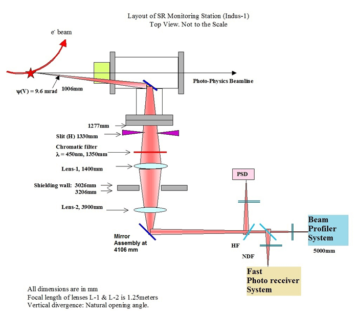
Figure 7: Diagnostic Beamline of Indus-1
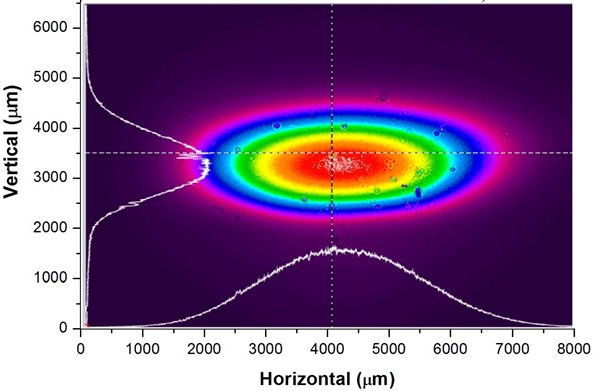
Figure 8: Typical snapshot of beam profiler system measured at experimental station in Indus-1
|


