|
Coolant Systems & Process Control Section (CSPCS)
The Indus accelerator machine houses two synchrotron light sources. The accelerator subsystems like Magnets, Power supplies, Photon Absorbers, RF cavities etc. get heated during operation either due to joules heating effect or because of radiation. Thermal consistency of accelerator systems is very imperative for maintaining beam energy and position stability which are remarkably helpful by providing proper cooling arrangement with precise temperature stability. As the Low Conductivity Water (LCW) flows through the machine cooling circuits which are subjected to radiation environment. The water chemistry is also an important factor to mitigate the possibility of having activation products. Deionized (DI) water is used as LCW coolant for cooling the accelerator subsystems due to following reasons:
- To avoid leakage of electrical current from the machine component’s metal surface :
Since, coolant water flows through the electrical power carrying metal core surfaces, a part of electrical current can be carried away by the coolant water, if the coolant is conducting.
- To avoid the electrical short-circuiting between system components :
Since various accelerator components are operated at different electrical potential, conductive water can cause short-circuiting and creating unsafe working condition which can damage the system components.
- To avoid corrosion / scaling effect on wetted surfaces :
Dissolved salts and impurities can increase coolant carrying surface corrosion (damaging the component being cooled) or scaling (hampering effective heat transfer during cooling). DI water has minimal salt content & provide clean working environment.
More detailed information about CSPCS is as below:
Mandate
- Design, Installation, Testing, Commissioning, Operation & Maintenance of Indus LCW Plants for cooling the Accelerator Machine Components.
- Providing services for development and installation of LCW Plants related to various other development Labs like IMA, ARPF, RF and Magnet Buildings.
- Development, Installation, Testing , Commissioning, Operation & Maintenance of Precision Cooling System (PCS) Units along with refrigeration cooling arrangement for conditioning the RF Cavity body with precise temperature stability of ± 0.1°C in the complete operating range of 20~79 °C.
- Development, Installation, Testing, Operation & Maintenance of Process Control Systems in CSPCS to communicate display of the coolant plants operating parameters in LCW plant control room & also in Indus Main Control room area to monitor the health of systems, remotely.
- Design, Installation, Testing, Commissioning, Operation & Maintenance of Cooling tower based and Refrigeration based secondary cooling systems to take away the thermal heat of accelerator machine through the plate type Heat Exchangers and provide conditioned primary coolant for the accelerator machine.
- Installation, Testing, Commissioning, Operation & Maintenance of water treatment plants for producing DI & Soft Water. The LCW Plants provide the required quality of coolants suitable for accelerator machine working environment.
- Upgradation, installation & mentainence of plant related components in the sectional fabrication and machine shop. Also takes care about development activities of different essential parts for ongoing activities of LCW plants, Chiller Systems, maintenance, piping works & Chemical Lab.
- Development and Installation of water analysis Lab, Thermal Lab, Instrumentation Lab, Flow calibration Lab and Temperature calibration set-up to maintain the required performance of system’s operating parameters with accurate data monitoring and Quality controlling of the coolants.
- Development of in-situ and offline chemical conditioning of Plate Heat Exchanger surfaces for restoring its heat transfer performance.
Specification
List of Installed & Operating LCW Plants:
| Sl No |
Location |
Capacity of Plant |
| 1 |
Indus – 1 LCW Plant |
600 kW |
| 2 |
Indus – 2 LCW Plant |
4000 kW |
| 3 |
IMA Building LCW Plant |
300 KW |
| 4 |
Magnet Testing Lab Plant |
200 KW |
| 5 |
ADL Building Cooling System |
20 kW |
| 6 |
ARPF Site LCW Plant |
300 kW |
List of Installed & Operating Precision Cooling Systems (PCS) & Chiller Plants:
| Sl No |
Details |
No of Units |
Max Cooling Capacity |
| 1 |
Indus-1 PCS units |
3 |
10 kW |
| 2 |
Indus-2 PCS units |
8 |
500 kW |
| 3 |
Indus-2 Chiller Plants |
2 |
2000 kW |
Specification for LCW Plant for Accelerator Machine:
| Plant Details |
Indus-1 |
Indus-2 SRS |
Indus-2 RF,PS,TL3 |
| Plant Cooling Capacity |
600 KW |
1000 KW |
2000 |
| Electrical Power |
120 kVA |
850 kVA |
| Primary Circuit |
|
| Flow Rate |
60 m3/hr |
110 m3/hr |
170 m3/hr |
| Supply Pressure |
10 kg/cm2 |
10 kg/cm2 |
10 kg/cm2 |
| Inlet Temperature |
30 ° C ± 1 °C |
26 ° C ± 0.5 °C |
26 ° C ± 1 °C |
| Electrical Conductivity |
< 1 µS/cm |
< 1 µS/cm |
< 1 µS/cm |
| Surge Tank Volume |
2 x 5.0 m3 |
7.5 m3 |
7.5 m3 |
| Secondary Circuit |
|
| Flow Rate (Max) |
120 m3/hr |
160 m3/hr |
300 m3/hr |
| Supply Pressure |
5 kg/cm2 |
5 kg/cm2 |
5 kg/cm2 |
| Hardness |
< 5 ppm |
< 5 ppm |
< 5 ppm |
| DI Circuit |
|
| Flow Rate |
0.5 m3/h (1m3/h max) |
1 m3/h (3 m3/h max) |
| Output Between Regenerations (OBR) |
~ 20 m3 |
~ 40 m3 |
LCW Plant Layout Photographs / Figures:
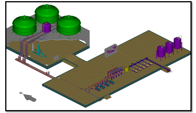
Figure1: Schematic view of the LCW Plant with the general layout of Primary & Secondary systems with CT
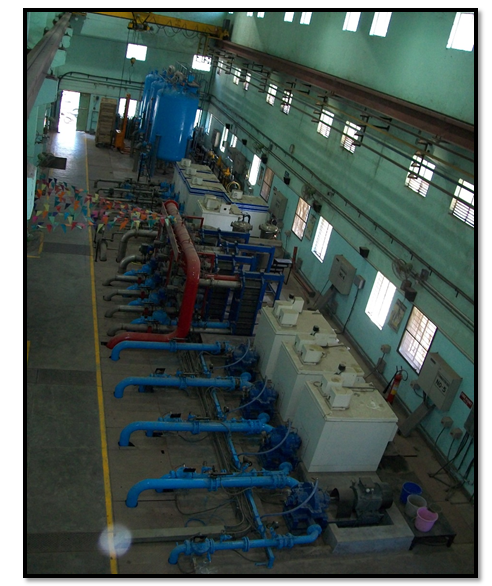
Figure 2: LCW Plant Service block Area view with Primary & Secondary Pumping Systems.
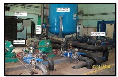
Figure 3: LCW Plant Indus-2 SRS cooling System view with PHE.
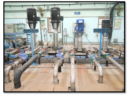
Figure 4: LCW Plant Primary Cooling System view.
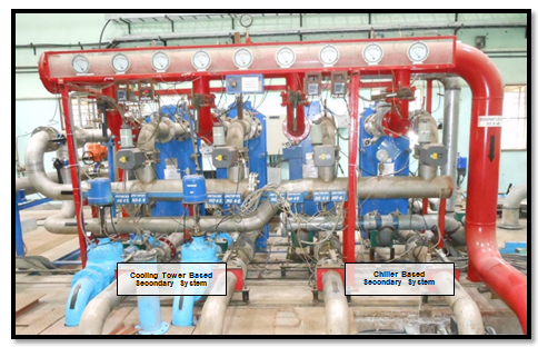
Figure 5: LCW Plant Heat Exchanger view with control valves arrangement
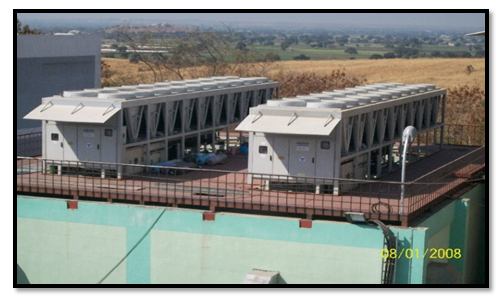
Figure 6: Refrigeration Cooling Chiller Units view in Indus-2 LCW Plant.
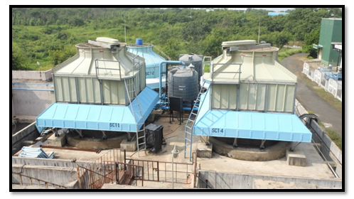
Figure 7: LCW Plant Cooling Tower view located on the terrace with makeup Tank
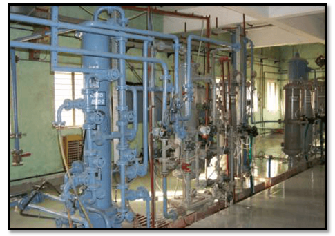
Figure 8: LCW Water Treatment Plant view
Refrigeration based Precision Cooling Systems (PCS):
Indus-1 Accelerator Machine related Chiller units
Table-1
S.No. |
Chiller Unit Details |
Qty |
Cooling Capacity (Each) |
1 |
Chiller Units for Microtron RFC |
2 |
1 kW |
2 |
Ring Chiller for Booster RFC |
1 |
3 kW |
3 |
Chiller-1 for SRS Ring RFC |
1 |
3 kW |
4 |
Chiller-2 for SRS Ring RFC (standby) |
1 |
10 kW |
Indus-2 Accelerator Machine related Chiller units
Table-2
S. No. |
Chiller Unit Details |
Qty |
Cooling Capacity (Each) |
PCS for RF Cavity (RFC) cooling |
-
|
Chiller unit Type -1 for LS-8 RFC |
3 |
65 kW |
-
|
Chiller unit Type-2 for |
2 |
90 kW |
-
|
Chiller unit type-3 |
2 |
210 kW |
Chiller Plant for SRS Cooling System |
-
|
Air Cooled Chiller units |
2 |
1000 kW |
Specification of Precision Cooling Units installed in Indus:
Table-3
Parameters |
Microtron |
Booster |
Indus-1SRS |
Indus-2 SRS |
Pump Flow Rate |
5 LPM |
30 LPM |
40 LPM |
12 m3/h |
Temperature Range |
20 ~ 30 ºC |
20 ~ 30 ºC |
20 ~ 31 ºC |
25 – 79 ºC |
Temperature Stability |
± 0.5 ºC |
± 0.5 ºC |
± 0.5 ºC |
± 0.1 ºC |
Refrigerant in Use |
R-22 |
R-22 |
R-22 |
R-22 |
Condenser |
Air Cooled |
Air Cooled |
Air Cooled |
Air Cooled |
Evaporator |
Dipped Tube |
Dipped Tube |
Brazed PHE |
Brazed PHE |
Heater Bank |
NIL |
NIL |
2 KW |
32 kW,
Insertion Type |
Temperature Control |
ON/OFF Ctrl |
ON/OFF Ctrl |
PID Control |
PID Control |
Precision Cooling Systems photographs and performance graphs:
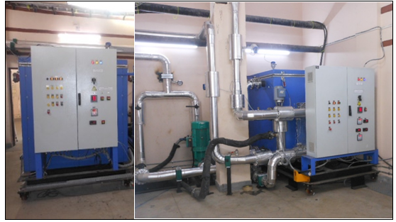
Figure 9: Precision Cooling Systems (PCS) for Indus-2 RF Cavity conditioning
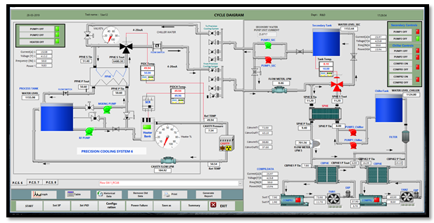
Figure 10: Precision Cooling Systems operation mimic view
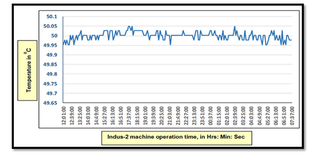
Figure 11: PCS supply temperature stability within ±0.1 ºC during Indus-2 operation at 2.5 GeV.
Development Activities & Facility in Coolant Systems & Process Control Section:
- Development of water analysis Lab as shown in Fig-12 & Fig. 13 for the coolant quality control, analysis of deposits and efficiency measurement of treatment media.
- Development of Flow Calibration Rig as shown in Fig. 14 to calibrate Flow Meters & Flow Switches
- Development of Thermal Lab as shown in Fig. 15 for checking the PCS operating parameters and development activities.
- Development of machine shop and fabrication area as shown in Fig. 16 to carryout CSPCS related maintenance works.
- Development of Hydraulic Lab as shown in Fig, 17 for hydraulic cum pneumatic testing of Plant related valves & pipeline fittings.
- Development of Instrumentation Lab for Calibration of Temperature sensor, transmitter & Controllers.
- Development for Utilization of TESS (Thermal Energy Storage System) in LCW Plant.
- Development of PHE plates conditioning setup for improving the heat transfer efficiency.
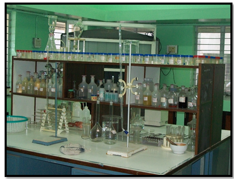
Figure 12: LCW Plant Water Analysis Laboratory.
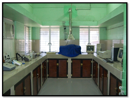
Figure13: LCW Plant Instrumental Analysis Laboratory.
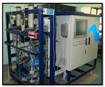
Figure 14: Flow Calibration Lab Test Setup
Figure 15: Thermal Lab Test Facility in CSPCS
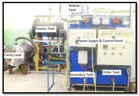
Figure 16: CSPCS Workshop & Maintenance Facility
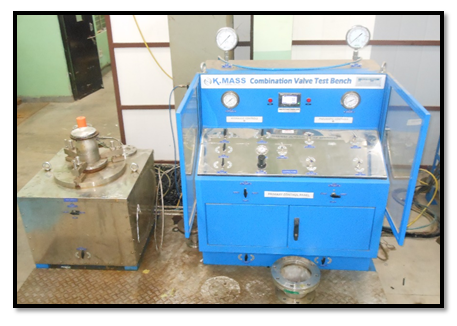
Figure 17: Hydraulic cum Pneumatic Valve Test Bench facility in CSPCS
|


