 Home Laser Controls & Instrumentation Division
Automation of Systems & Laboratory Experiments
LCID has been providing automation support for various laboratories in RRCAT. We have successfully accomplished automation and delivered data acquisition systems for experiments of wide variety and are constantly providing support for upcoming requirements.
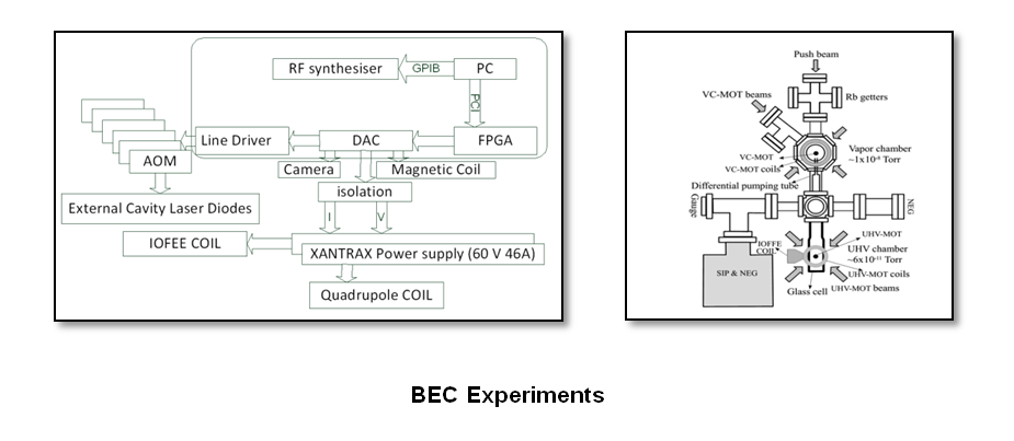
Automation of BEC Experiments and Atom Chip MOT Experiments
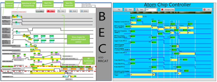
Bose–Einstein condensate (BEC) state of the matter is generated when a dilute gas of bosons confined in an external potential, is cooled to very low temperature in the range of few hundred nK to few μK. In order to achieve BEC, the precise control of multiple devices is absolutely essential. There are number of devices which are operating synchronously, such as Acousto Optic Modulators, RF synthesizer, magnet power supplies, camera trigger etc. We have designed a computer controlled automation system. Software for this system is developed in Labview platform. We have used commercially off the shelf FPGA hardware with PCI interface to achieve timing synchronization, resolution & accuracy of 1 µs. The timing jitter of 25ns (max) between 14 such control signals is achieved with this dedicated hardware. Digital output ports of FPGA are connected to in-house developed module consisting of seven 12-bit DAC cards. Each 12-bit DAC require 12-bit data and three digital control lines. In all 105 digital data lines of FPGA are used to generate 7 analog outputs. These cards translate the timing signals to appropriate voltage signal and provide 50 ohm load drive capability. We have developed two software applications. First target software runs on PCI-FPGA card to generate precisely synchronized analog signals. The other software runs on PC which provides Graphical User Interface (GUI) for users to conduct BEC experiments.
To perform Atom chip experiments similar synchronized generation of 8 digital and 14 analog signals (6 isolated + 8 with capability to drive 50 ohm load). NI 7841R card with on-board FPGA and mixed signal outputs is used for this application. Digital outputs are used to generate synchronization signals while analog outputs are used to generate analog ramp signals with precision timing. Separate 8-channel drive module was developed for driving 50 ohm load. FPGA ensures parallelism and reliability. The developed target software runs on FPGA card. The PC software provides user friendly GUI for experiments.
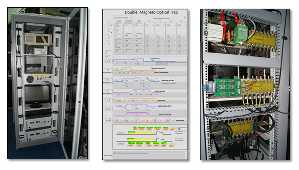
Automation of Double Magneto Optical Trap (MOT) Experiments
A PAC based system is designed to automate double MOT experiments. The controller provides control signals to laser, magnet power supplies, mechanical shutters and camera. Controller is interfaced to commercial of the shelf (COTS) instruments so that operation of these instruments can be controlled by PC. These instruments include PID temperature controller and pressure controller. The timing resolution of the control system is 1 microsecond. It has isolated analog I/O with 16-bit resolution and 50 ohm load drive capacity. Controller has 15 analog control signals and 11 digital signals. The control software running on PC has GUI for ease of operation. GUI provides reconfigurable inputs for 111 control parameters like voltage, current, time delay, step, ramp, pattern etc.
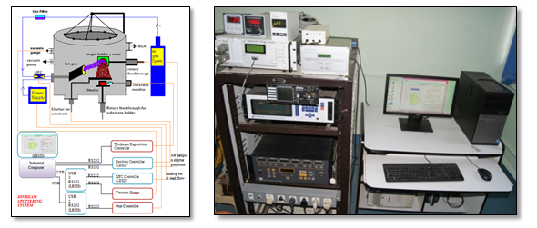
Automation of Ion-Beam Sputtering System
An Ion-Beam Sputtering (IBS) system has been developed by ISUD for fabrication thin film multilayers of various elements, alloys and compounds on a suitable substrate material. The multilayer fabrication is carried out by depositing layers of varied thickness by ion beam sputtering. The entire deposition process is performed inside a vacuum chamber.
LCID has developed PC based controller which automates the multi-layer fabrication process. The process consists of number of pre-determined steps to fabricate multilayer. The process is time consuming and need constant monitoring. By automation we have eliminated manpower requirement and associated human errors. Due to automation fabricated multi-layer specimens have repetitive characteristics.
The process consists of 4 target material mounted on one rotation mechanism. The material which is to be deposited is rotated and brought in front of ion beam with help of stepper motor. Ion beam is stopped with help of mechanical shutter. Operation of this shutter is controlled by another stepper motor. In-house developed two channel stepper motor controller is used to move target and to control shutter. The chamber has inlet for inert gas. A mass flow controller is installed to control flow of gas inside the chamber. In house developed readout module reads the gas flow. This readout has RS-232 interface with PC. System has other instruments like ion deposition controller, thickness gauge, gun controller, pressure gauge, vacuum gauge. These instruments are interfaced with control PC for remote operation. Thickness gauge is used to measure thickness of the deposited thin film. Once the desired thickness is reached control system stops the beam with help of shutter and changes the target material by rotating the target holder and then again removes shutter to continue deposition. Once desired layers are built system automatically stops and alerts user.
Automation software was developed in Labview to facilitate user to fabricate 100s of layer pairs of selected materials in an automated fashion. The software provides multilayer and monolayer deposition and also fixed thickness or fixed time deposition. It is observed that human errors occurring in the sample preparation process due to fatigue of operator and lack of timely action are totally eliminated. A good degree of repeatability in sample quality is observed. This automation also saves a great deal of time. Earlier dedicated man power was required which is no longer mandatory as sample preparation process can be left unattended. The rate of production of usable samples has greatly increased.
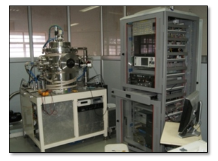
Supervisory control system for Ion Assisted Sputter Deposition System (IASDS)
In sputtering, material to be deposited is first sputtered (atomized) by ion bombardment in plasma and there by transformed to vapour phase. The particle vapour is then deposited as a thin film on the substrate to be coated. The system is pumped with turbo molecular pump and backed by rotary pump. This sputter unit is equipped with two magnetron guns. RF, DC, pulse DC power can applied to the individual magnetron. Sputtering of single material, co-sputtering of two materials, sequential sputtering of two materials and reactive sputtering (with gas mixtures) can be carried out in the system. Each Material thickness can be monitored independently with a quartz crystal monitor. The In house developed sputtering system provides versatile options to meet many deposition requirements like multilayer optical coatings, thin film research, magnetic devices etc.
An OMRON make CPU CJ2M/CPU13 with RS232 and USB interface PLC based control system is developed for IASDS. This system will facilitate operation in remote mode (through PC) and local mode (through local panel). The system has the capability of 128 nos. of digital inputs, 128 nos. of digital outputs, 24-channel 12-bit analog inputs/outputs to control remotely interfaced devices. For Graphical User interface Labview is used. As Labview OPC server supports OMRON make PLC CPU CJ2M/CPU13.
Automated Test Bench for Accelerator Magnet Power supplies
Power supplies of accelerator magnets are designed and developed in RRCAT by Accelerator Power Supply Division. These accelerator power supplies are usually operated in round the clock operation. Hence, rigorous testing of these power supplies is carried out before installing them in field. These tests include functional testing of the power supply, checking stability of output, monitoring output current drift over period of time and checking stability of power supply control loop for standard waveforms like ramp, staircase, step input. These stability tests are essential since power supply will see similar demand during its useful life. Apart from this, accelerated tests of each power supply are essential to eliminate infant mortality of the power supply.
These tests cannot be performed manually, since these need setting of multiple parameters and recording the data manually with various test and measuring instruments. In case of accelerated test procedure repeated operation can be monotonous and may result in operator fatigue, which may lead to erroneous results. Sometimes configuration of Test & Measuring instruments need advance operator skill which can be under utilization of trained manpower. Moreover all manually recorded data has to be fed to computer for presentation & analysis. Some tests need warming up of power supply which can be in hours so utilizing manpower can be a challenge. In view of above challenges an Automated Test Bench (ATB) is designed & developed.
APSD & LCID have jointly developed test bench for testing of Accelerator Magnet Power Supplies. LCID was responsible for development of Controller which operates the power supply. Automation software with Graphical User Interface (GUI) was developed to perform various tests on power supply. The software accepts the test parameters from user at the beginning of test and configures commercially available of the shelf (COTS) instruments accordingly. Automation software then acquires data, analyzes steady state response, transient response and stability. Software performs data analysis as defined in test sequence. Software presents this data in graphical form for easy understanding. Software also provides calibration check facility for bench. After completion of scheduled tests, a detailed report with graphs and tabular documentation is generated for future reference.
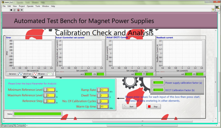
GUI for ATB
Automation Software for Characterisation of Femtosecond Laser Pulses using Autocorrelation and FROG
Two techniques namely auto-correlation and FROG (Frequency Resolved Optical Gating) are most widely employed to determine laser pulse characteristics. The laser pulse itself is used to measure the response using nonlinear optical techniques. Intensity autocorrelation is a simple technique to measure pulse duration. FROG is relatively advanced technique which provides phase information in addition to the information obtained by intensity autocorrelation.
In order to characterize these pulses a setup consisting of an optical setup and relevant instrumentation was developed. Automation software which runs on an industrial computer (IPC) was developed in Labview in order to take measurements and present results. The automation process involves the control and monitoring of the spectrometer, photodiode and delay stages in order to characterize the pulse in real time.
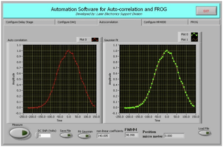
GUI for Autocorrelation and FROG measurements
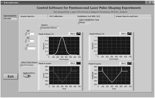
Automation Software for Femtosecond Laser Pulse Shaping Experiments
Intensity modulated femtosecond laser pulses are used in many ultrafast spectroscopy experiments to control and study the molecular photo-processes. In these experiments spatial light modulator (SLM) is used to intensity modulate the laser pulses and thus achieve the desired laser pulse shape. Spectrometer is used to record the spectrum of the resultant laser pulse. We have developed PC based automation software in Labview to generate desired function shape from provided list of functions like constant voltage, gaussian, parabola, triangle, well and step. The user can set multiple coefficients and thus obtain any desired laser pulse shape in automated fashion. This pattern is then applied to SLM and monitored by spectrometer. An external pattern can also be given from a file, if user wants to use some customized function input other than provided functions.
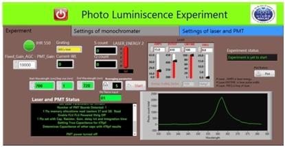
Automation of Photoluminescence Experiment
Photoluminescence study of semiconductor material especially nitride semiconductor is carried out by semiconductor Physics and devices lab. Software aims to provide parameter control of monochromator, laser, and PMT and experiment procedure. Graphical user interface is developed to facilitate the display of experiment data, state of experiment and analysis of data.
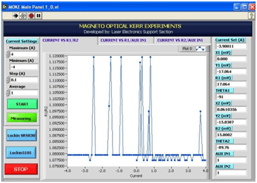
Automation of Magneto Optic Kerr Effect(MOKE) Experiment
Software is developed to carry out MOKE experiments. It is used to control laser, magnet power supply and detection via lock-in amplifier. The data is logged from various subsystems and presented in the form of waveform for analysis. To conduct MOKE experiments, a B-H curve has to be followed by magnet power supply, which is achieved by automation of the process.
Automation of Opto-Galvanic Spectroscopy experiment:
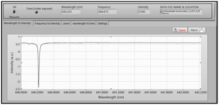
A computerized system has been developed for automation of opto-galvanic spectroscopy experiments conducted using in-house developed copper vapour pumped tuneable dye laser at RRCAT. In this experiment precise tuning of dye laser and measurement of opto-galvanic signals are required to be carried out. Automated tuning and scanning of dye laser is carried out by interfacing of precise movement controlled translation stage through USB based multifunction card and wavelength meter. Photodiode captured the opto galvanic signal and coerced it in to electrical signal which is further processed using boxcar averager. The output of boxcar averager is acquired using USB based analog input card. Software with Graphical user interface is developed using Labview which provides monitoring of opto galvanic signal intensity with respect to wavelength, recording of wavelength and intensity data for further analysis, settings for control parameters of translation stage, wavelength input. Wavelength scanning and tuning setup is also being used for wavelength stabilization of dye laser.
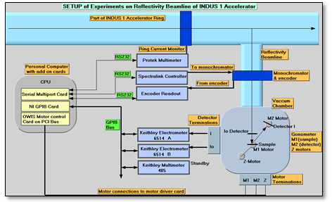
Data Acquisition and Control System for INDUS1-BL4 Reflectivity Experiments
A Supervisory data acquisition and control system has been developed for automation of experiments conducted on reflectivity beamline of INDUS-1 accelerator. These experiments help us to study characteristics of multilayer mirrors. There are various equipments installed on these beamlines. These equipments are monochromator for wavelength selection, goniometer for positioning sample and detector, beam & ring current monitors to measure beam parameters. Apart from this, there is motorized filter to attenuate beam intensity. Monochromator has encoder as feedback element, where as goniometer has micro stepping motors for positioning.
These instruments are controlled & monitored for performing experiments on the beamline. LCID has developed software for automation of experiments performed using reflectivity beam line and delivered module for filter wheel alignment. The software developed provides complete automation of four categories of experiments involving continuous scan (simultaneous movement of sample and detector maintaining theta-2theta correspondence), wavelength scan, angle scan and time scan. It provides control of goniometer movement separately for alignment and initial setup of experiment. The user has facility to view & store online plots of experiments. These experiments are carried out with high degree of precision and repeatability.
Other Automation Projects
- Automation Software for Resonance Ultrasonic Spectroscopy Experiments
- Automation of Transient Spectroscopy Experiments
- 2-D Beam Profiling for THz Radiation
- THz field auto-correlation Measurement
- Ultrafast Plasmonics Software
- Time resolved pump-probe reflectance measurements
Process Interrupt Handling System (PIHS) at ARPF
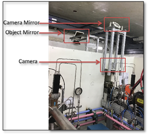
PIHS is a machine vision based system developed for resumption of irradiation of product box at correct position in case of beam trip. The system is installed at ARPF. Previously, the location of beam trip was unmonitored and the product box under irradiation had to be discarded in case of beam trip. The resumption process was also not smooth. After installation of this system, if beam gets interrupted, then product is irradiated from the same point at which beam trip occurred.
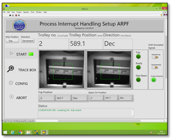
The PIHS system is suitably designed to sustain the radiation exposure. Vision based method allows positioning of camera after shielding wall to minimize radiation on sensor. The image is transported via two mirrors placed suitably at 45 degrees, one above product box and other above camera. PIHS system consists of image transportation, image acquisition, image transfer to control room PC through Ethernet and hardware module for synchronization. Software is deployed on PC for image processing, analysis and resumption of machine by receiving and giving proper synchronizing signals to associated systems, namely beam pulse monitoring system and main control system. The system continuously monitors product boxes passing on conveyer and records their instantaneous position in front of beam. PIHS enables measurement of product box position and resumption of beam for irradiation within 5mm of beam trip position on product box.
| |
PIHS Setup | GUI in Control Room |
Control System for Cold Atom Gravimeter Experiments
Cold atom interferometry experiments are carried out in order to derive cold atom gravimeter measurements. It consists of processes such as laser cooling of Rb atoms, stabilization and compression of cold atom cloud, cooling in optical molasses etc. These events are controlled from devices such as Acousto-Optic Modulators (AOM), Power Supplies, and Mechanical Shutter which needs synchronised control with timing resolution of 1 microsecond for the events ranging up to 10s of seconds. Each device needs to be controlled from dedicated control channels. Thus required numbers of control channels are:
| 1. | Analog Channel with programmable ramp sequence generation | 24 |
| 2. | Analog Channel with programmable step sequence generation | 08 |
| 3. | Digital Channel | 24 |
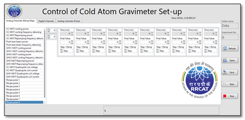
A PAC based system is developed to allow generation of these control channels in 10 time steps. These control channels can be configured at PC in a graphical user interface (GUI). GUI lists the entire available channel at left panel, which are selectable. Once selected, it enables configuration of all the control variables. Time step are configurable in units of milliseconds or microseconds. Control steps are configurable for its shape in the form of ramp or step. Output Voltages are configurable in the range of 0 to 10 V.
|
GUI for Control System of Cold Atom Gravimeter Experiments |
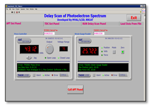
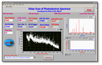
DAQ System for Delay Scan Photoelectron Spectroscopy Experiments used for Reconstruction of Attosecond Pulse
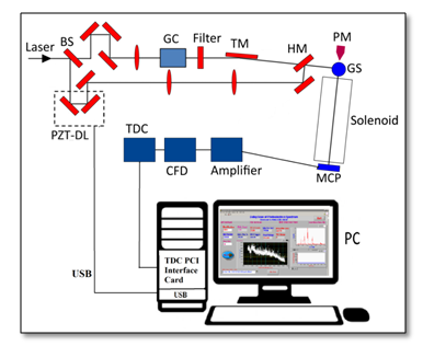
Reconstruction of attosecond pulse generated by higher harmonics of femtosecond laser pulse is carried out by delay scan photoelectron spectroscopy technique. For reconstruction of attosecond pulse, huge set of data is required to be input to frog-crab algorithm of pulse reconstruction, which runs on computing server. Data acquisition in experimental studies of delay scan photoelectron spectroscopy experiments becomes tedious when one needs to acquire data by synchronizing two or more equipments for very long duration. This introduces an added difficulty, since multiple data points are acquired in a short time. In such scenario, human error can render all data useless. Hence, automation of experimental setup becomes essential. A PC based DAQ system including automation software are developed which generates 2-d spectrogram data from electron time of flight spectrograph acquired from time to digital converter(TDC) in synchronization with a piezoelectric translation stage (PZT).
The experimental setup is used to generate the attosecond XUV pulses and characterize their temporal profile. A 1 kHz, 6 mJ, 50 fs Ti:Sapphire laser is used in as a source of XUV pulses. The TDC used is Roentdek GmbH Model: TDC8HP with resolution of 25 picosecond and range ~1 nanosecond to 1 microsecond having PCI interface to PC. The PZT delay stage is Thorlabs Model: PAZ 009 having resolution: 10 nm and range ~40 micron having USB interface. A typical experiment runs for around 12 hours and the developed DAQ software generates ~2000 no. of 2-d spectrogram files for each run. The large no. of data files thus generated by the software, are fed to server running computational frog-crab algorithm. The algorithm then generates the attosecond pulse temporal profile. This automation work is carried for LPD, RRCAT.
|
Experimental Setup |
|
|
GUI for Delay Scan Photoelectron Spectroscopy Experiments |
|