| Laser Physics Applications Division |
 Home Laser Physics Applications Division
Atom Optics Laboratory (AOL)
Objective and relevance of the activity
Home Laser Physics Applications Division
Atom Optics Laboratory (AOL)
Objective and relevance of the activity
Over more than two decades, there has been enormous progress in generation and manipulation of cold atoms for basic research and practical applications for various purposes. The development of precision atomic clocks, ultra-precise inertial sensors (accelerometer, gyroscope, gravimeter and gravity gradiometer etc.), nano-lithography, cold electrons and ions sources, etc. are few examples. In world scenario, work on cold atoms is at very advanced stage and several labs are actively involved in R & D work in this area of cutting-edge research and advanced technology.
The objective of laser atom cooling activity at RRCAT is to generate ultra-cold samples and Bose Condensates of atoms for study of basic science as well as for developing sensitive atom-optics devices for metrology and precision measurements. The scope of the work also includes the demonstration of new trapping geometries using static magnetic field, combination of radio-frequency field and static magnetic field, far detuned focused laser field, periodic/ structured laser intensity fields etc. With the objective of achieving atom trapping on miniaturized scale for compact atom optic devices, efforts are being made to trap and manipulate cold atoms on the atom-chip. This will pave the way for making compact atom-optics devices for sensing, metrology and quantum information using cold atoms.
Recent activities and achievements of the project :
(i) Cold atom gravimeter setup.
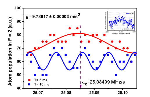
The cold atom based gravimeter for precision measurement of earth's gravitational acceleration (g) is under development. The initial results have shown the accuracy of g measurement as g = 9.78617±0.00003 m/s2.
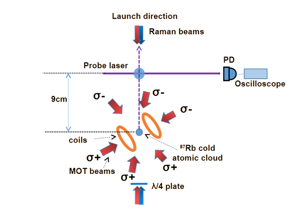
The magneto-optical trap (MOT) of 87Rb was formed in a three-fold symmetry [111] geometry around the vertical axis (Figs. I.1 and I.2). The cold atoms at a temperature of ~ 25 μK were launched vertically to form an atomic fountain. The Raman pulses (connecting F = 1 and F = 2 of ground state of 87Rb) were used for atom interferometry with sequence as π/2-T-π-T-π/2, where π pulse duration was 12 μs and separation T = 5 ms, 10 ms and 15 ms. The frequency of one of the Raman beams was chirped to compensate the change in Doppler shift due to gravitational acceleration ‘g’. The common maximum of interferometric fringes for two values of T, enabled us to know the central chirp rate (αc), which is required to compensate the phase shift due to g. As shown in the Fig. I.3, this chirp rate is estimated to be 25.08499 Mhz/s, which gives acceleration due to gravity ‘g’ as 9.78617±0.00003 m/s2. Further work is in progress to improve the accuracy and precision of measurement of ‘g’.
The long term aim of project is to develop a portable sensitive gravimeter for exploration of underground minerals. The other possible applications may be in monitoring seismic activities and in space science and technology.
|
Fig. I.1: Schematic of the cold atom gravimeter. |
|
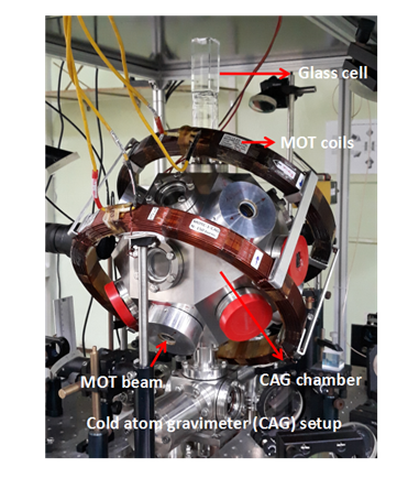
Fig. I.2: Photograph of the cold atom gravimeter setup for precision measurement of "g". |
|
Fig. I.3: Atom interferometry fringes for g measurement. The inset picture shows the experimental data for precise scanning of the frequency chirp rate around the central chirp rate (αc). |
(ii) Atom trapping on atom-chip setup:
We have developed a setup for trapping atoms on atom-chip. The aim of this work is to develop expertise in trapping and manipulation of atoms on miniaturized scale so that more compact and sensitive atom-optic devices can be developed. The following are the steps taken for performing atom trapping in magnetic traps of micro-wires on the atom-chip.
- Operation of mirror U-magneto-optical-trap (U-MOT) for 87Rb atoms on atom-chip.
- Operation of compressed MOT (C-MOT) and magnetic trapping of 87Rb atoms in external IP magnetic trap.
- Operation of grey-MOT (G-MOT).
- Trapping of atoms in magnetic trap due to micron size wires on the atom-chip.
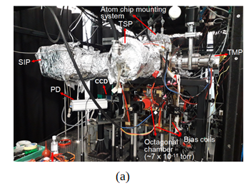
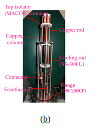
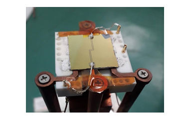
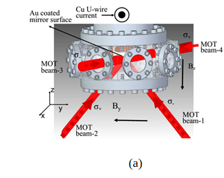
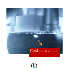
For trapping atoms on miniaturized scale for compact atom-optic devices, a setup for trapping atoms on atom-chip is being developed. The Figure II.1 shows the atom-chip setup and atom-chip mount assembly system. Figure II.2 shows the photograph of chip. The atom-chip mount assembly is vertically placed inside the vacuum chamber with chip facing vertically downwards. Atom chip (Figure II.2) was fabricated using Si substrate of size 25 mm x 25 mm (700 µm thick) after depositing the gold (Au) layer of 2.5 µm. The chip also serves as a mirror surface for mirror-MOT formation. The optical layout for the formation of mirror magneto-optical trap (MOT) is shown in Figure II.3. In the mirror U-MOT on chip, 87Rb cold atom cloud is formed few mm below the atom chip surface. The atom cloud in U-MOT had ~ 5 x 10⁷ atoms at temperature of ~300 µK.
|
|
|
Figure II.1: Photographs of (a) atom-chip setup and (b) atom-chip mounting system. |
|
|
Figure II.2: Photograph of in-house developed atom chip having single Z-shaped gold wires. |
|
|
|
Figure II.3: (a) MOT laser beam delivery in vacuum chamber for mirror-MOT. (b) CCD image of 87Rb cold atom cloud in U-MOT below the chip surface. |
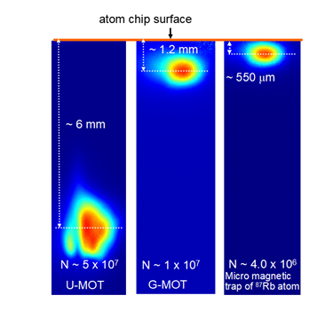
Next, the compressed MOT (C-MOT) stage was prepared in which cold atoms MOT cloud was moved vertically upward in z-direction to a position ~ 1.2 mm from the chip surface. The was done by ramping the current in U-wire (from 60 A to 80 A ) and in Y-bias coil (from 15 A to 40 A) in 100 ms duration. During this compression, the cooling laser frequency detuning is set at ~ -20 MHz to reduce the multiple scattering processes within the dense cloud. Then, grey-MOT (G-MOT) is prepared in ~ 10 ms duration by varying the cooling laser beam detuning from -30 MHz to -75 MHz. The cold atom number and temperature are measured and found to be ~ 1x10⁷ and 70 μK respectively in G-MOT.
The magnetic trapping of cold 87Rb atoms in Ioffe-Pritchard (IP) type trap formed by magnetic field due to a current carrying Z-shaped micro-wire (200 µm x 2.5 µm cross-section) on atom-chip has been demonstrated. This IP micro-magnetic trap is created by the combination of field due to above current carrying Z-shaped gold micro-wire on a chip and a bias magnetic field. The number of atoms trapped in the micro-magnetic trap was ~4 x 10⁶ with a life time of 60 ms. Work is in progress to enhance life time and number of atoms in the micro-trap. Figure II.4 shows the atom cloud in U-MOT, G-MOT and micro-magnetic trap.
|
|
Figure II.4: CCD images of cold 87Rb atom cloud in U-MOT, G-MOT and micro-magnetic trap. |
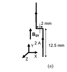
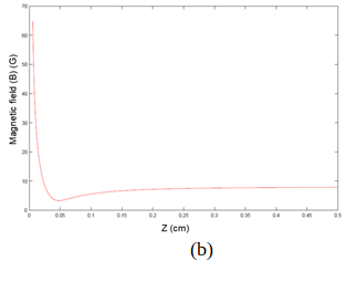
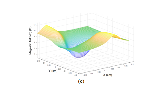
A typical Z-wire Magnetic Trap is shown in Figure II.5, where I is the current in the Z-wire and B0 is the external bias field along y-direction. Figure II.5 (b) shows the field due to Z-wire (I = 2 A) in presence of the bias field B0 = 9 G. It is clear from Figure II.5 (b) that magnetic field at the minimum is non-zero. The trap centre is located at (0, 0, 0.047 cm) from Z-wire at 2 A current and 9 G external bias field. Figure II.5 (c) shows the variation of the field in xy-plane for above current and bias field. The trap depth in Y- and Z- direction is ~ 700 μK whereas in X-direction, it is ~ 250 μK. Thus a Z-shaped wire provides a 3-dimensional confinement like a Ioffe-Pritchard trap.
|
|
|
|
Figure II.5: (a) Configuration of Z-type wire carrying current I, the homogeneous bias field (B0Y) applied in y-direction. (b) Spatial distribution of magnetic field along z-direction. (c) Magnetic field distribution in xy-plane at a selected value of z = 0.47 mm. The magnetic trap centre is at (0, 0, 0.47 mm). All the above figures are obtained at wire current of 2 A and bias field of 9 G. |
(iii) Trapping and manipulation of cold atoms using static magnetic, RF and optical fields.
This activitity is oriented to develop skills in trapping and manipulation of cold and ultracold atoms using different techniques and methods. On this setup earlier, we have demonstrated experimentally magnetic trapping of laser cooled Rb atoms in quadrupole trap and QUIC trap. Then applying RF-evaporative cooling in QUIC trap, Bose-Einstein condensation (BEC) was observed. Presently, the efforts are being made to develop new and versatile trapping methods based on fundametal physics principles. These methods may be an effective alternative to the existing trapping and manipulation techniques. The following activities are underway on this setup:
- Trapping of atoms in RF-dressed potentials and time average adiabatic potential (TAAP) in different geometries.
- Trapping of atoms in optical dipole trap (ODT).
Brief description of trapping of atoms in ODT:
The cold 87Rb atoms from a magneto-optical trap have been trapped in a single beam optical dipole trap (ODT). The ODT was formed by focusing the output of a fiber laser system operating at 1064 nm wavelength.
|
|
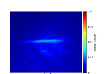
Figure III.1: The experimental optical density images of the trapped atom cloud obtained by absorption imaging. |
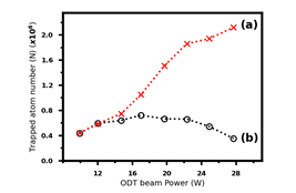
Figure III.1 shows the experimental optical density images of the trapped atom cloud obtained by absorption imaging. The effect of AC-Stark shift of atomic energy levels due to the ODT has been evaluated and its effect on in-situ absorption imaging of the trapped atoms has also been investigated. The spatially varying AC-Stark shift of energy levels due to ODT beam results in position dependent absorption cross-section of the atom at absorption probe laser wavelength, which significantly modifies the measured optical density (OD) of the atom cloud during the in-situ absorption imaging of the trapped cloud. In view of this, after taking AC-Stark shift into account, the analysis of measured in-situ absorption images of atom cloud has been revisited to estimate the correct number of atoms trapped in the ODT. The variation in number of atoms after incorporating the AC stark shift has been shown in Figure III.2. This work can be particularly useful in estimating the in-situ loss rate of atoms from the trap during the evaporative cooling of the trapped atom cloud.
|
|
Figure III.2: Variation in the number of atoms trapped in optical dipole trap with the power of the ODT beam, (a): after incorporating AC-Stark shift and (b): without incorporating the AC-Stark shift. |
Earlier Achievements
(A) UHV pressure measurement by MOT loading method:
The measurement of ultra high vacuum (UHV) pressure from the magneto-optical trap (MOT) loading data is reported here. The loading time (τL ) and saturated number (Ns) for a MOT loaded from the background vapor depend on the pressure in the chamber. The partial pressure due to Rb-vapor can be varied by varying the dispenser source current. By measuring Ns and tL from MOT loading data at different values of dispenser current, the partial pressure due to Rb-vapor (PRb) and background pressure (P) due to non-Rb gases have been estimated. It is found that estimated pressure at MOT position (near to dispenser) is much different from the pressure read by the sputter ion pump (SIP) attached away from the MOT position. This precise knowledge of pressure at MOT position is important for further work on magnetic trapping. This method of pressure measurement reported here has a potential in developing the UHV as well as extreme-high vacuum (XHV) pressure standards.
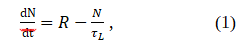
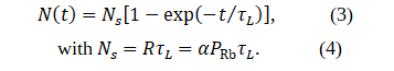
The loading of atoms in a MOT is governed by the rate equations,
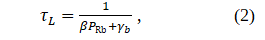
where N is the number of atoms at any time (t) in the MOT, R is the MOT loading rate and tL is the MOT loading time. The loading time (tL ) depends upon the partial pressure (PRb) due to Rb atoms as well as pressure (P) due to non-Rb atoms/molecules in the chamber. It is given as,
where the term βPRb represents the collisional loss rate due to untrapped Rb atoms and γb represents the collisional loss rate due to non-Rb atoms/molecules.
The solution of equation (1) can be written as,
Here, Ns denotes the saturated number in the MOT and α is MOT trapping cross section. From equations (2) and (4), the relation between Ns and tL is given as,
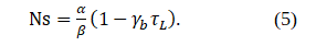
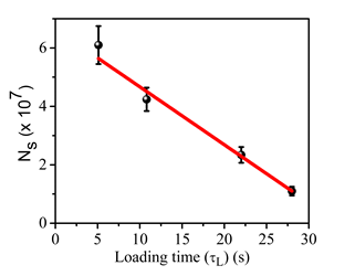
By measuring the variation in Ns with tL , the parameters α/β and ɣb can be obtained by fitting the measured data with equation (5). We have measured Ns and tL by fitting equation (3) to the measured MOT loading data at a given dispenser current (Fig.A.1). Then variation in Ns with tL was obtained by changing the Rb-dispenser current and measuring Ns and tL . This plot is shown in Fig.A.2, which gives α/β=(6.65±0.30)x107 and ɣb =(2.90±0.06)x10-2 s-1 after a fit to equation (5). Using these values obtained from the fit, and β=4.4x10⁷ Torr-1 s-1 and ɣb /P = 4.9x10⁷ Torr-1 s-1 from the literature, we can estimate the partial pressure due to Rb-vapor PRb ( PRb = Ns/(αtL) ) and the background non-Rb gas pressure (P= ɣb /( 4.9x10⁷) in the chamber. Using this method, the estimated non-Rb gas pressure in our UHV chamber (for atom-chip MOT) is ~5.9x10⁻¹⁰ Torr. The estimated partial pressure values due to Rb vapor are ~1.4x10⁻¹⁰ Torr and ~4x10⁻⁹ Torr at dispenser current values of 2.8 A and 3.4 A respectively.
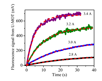 Fig.A.1. Increase in MOT fluorescence signal (i.e. number of atoms in MOT cloud) with time during loading of MOT at different values of dispenser current (figure reference, V Singh, V B Tiwari, S R Mishra, Laser Phys. Lett. 17(2020)(035501)). Dashed curves show a fit to equation (3).
Fig. A.2 : The measured variation in Ns with tL and a fit to equation (5) ( figure reference, V Singh, V B Tiwari, S R Mishra, Laser Phys. Lett. 17(2020)(035501)).
(B) Trapping cold 87Rb atoms in a toroidal trap using an RF-dressed magnetic trap
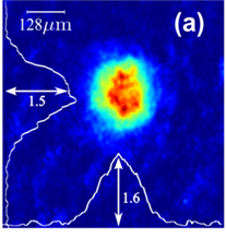
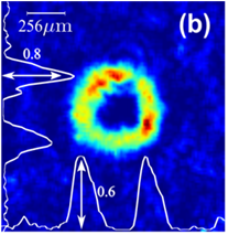
The evaporatively cooled atom cloud was also trapped in a toroidal trap using an RF-dressed mag-netic trap. The RF-dressed potential was generated by applying a strong RF-field in presence of a static quadrupole magnetic trap used for trapping of laser cooled 87Rb atoms. The picture of atom cloud trapped in toroidal geometry is shown in Figure. B.1. Such toroidal trapping can be useful to study behaviour of ultra-cold gases in low dimensions. The potential landscapes generated using RF-dressing of magnetic traps can be easily manipulated by varying RF field parameters such as frequency, polarization, amplitude and phase.
|
|
|
Figure B.1: Image of atom cloud in (a) quadrupole magnetic trap and (b) RF-dressed toroidal trap. |
(C) Achievement of Bose-Einstein condensation of 87Rb atoms in double MOT setup
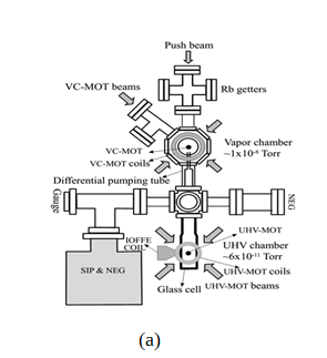
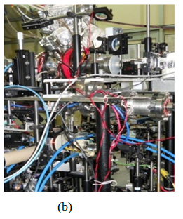
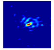
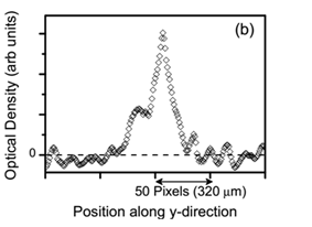
The experimental setup to produce ultracold 87Rb atoms and their Bose-Einstein condensation (BEC) has a double magneto-optical trap (double-MOT) configuration. The double-MOT setup (Figure C.1) consists of a vapor chamber MOT (VC-MOT) at ~1-2 x 10⁻⁸ Torr pressure and an ultrahigh vacuum MOT (UHV-MOT) at ~5x10-11 pressure. This setup involves magnetic trap for cold atoms, RF evaporative cooling system, detection and characterization system, and a PC-based controller system to implement various cooling stages in a desired sequence. Here the UHV-MOT atoms are subjected to magnetic trapping and evaporative cooling to achieve BEC. Figure C.2 shows an image and spatial profile of optical density of cold atom cloud after evaporative cooling performed using this setup in the lab. The sharp peak at the center in this profile shows the presence of Bose-condensate in the cloud.
|
|
|
Figure C.1: (a) Schematic and (b) photograph of the double-MOT setup. |
|
|
|
Figure C.2: (a) An observed image and (b) spatial profile of optical density of an ultracold atom-cloud with Bose-Einstein condensate at the center. |
(D) Laser cooling of various bosonic (82Kr,84Kr and 86Kr) and fermionic (83Kr) isotopes of Krypton atom
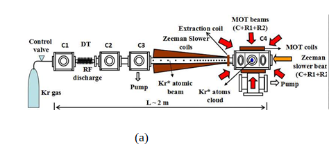
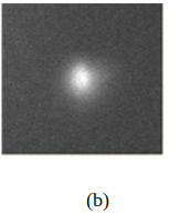
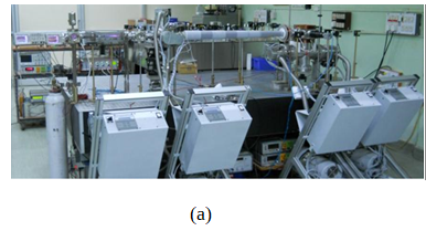
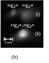
The experimental setup to cool and trap noble gas metastable Kr atoms along with the CCD images of the cold atom are shown in the Figures D.1 and D.2. The Krypton gas first flows into RF discharge glass tube through the gas inlet chamber, where metastable atoms of Kr are prepared. These metastable atoms, after slowing down in a Zeeman slower device, are transported to MOT chamber (~10-8 Torr). In this MOT chamber, the Kr atoms are cooled and trapped using cooling and repump-ing laser beams alongwith appropriate quadrupole magnetic field. The laser cooling of various bosonic (82Kr, 84Kr and 86Kr) as well as fermionic (83Kr) isotopes of Krypton has been successfully demonstrated. In addition, dual-isotope MOTs (Figure D.1) for cold bosonic-bosonic and bosonic-fermionic mixtures have been demonstrated. The dual-isotope MOTs are useful to study cold colli-sions among various species.
|
|
|
Figure D.1: Schematics of the experimental setup for laser cooling of 83Kr* atoms. C1: Kr gas inlet chamber, C2: Analysis chamber, C3: pumping chamber, MOT: magneto-optical trap, C: cooling beams, R1 and R2: repumping beams. (b) CCD fluorescence image of cold atom cloud of 83Kr* atoms. |
|
|
|
Figure D.2: Photograph of the experimental setup for laser cooling of Kr atoms. (b) CCD fluores-cence images of separated and overlapped cold atom clouds of Kr* atoms in a dual-isotope MOT. |
Publications
Some recent publications
-
“Development and characterization of atom chip for magnetic trapping of atoms”,
V. Singh, V. B. Tiwari, A. Chaudhary, R. Shukla, C. Mukharjee, S. R. Mishra.
J. Appl. Phys., 133, 084402, (2023).
- "A method for loading magneto-optical trap in an ultrahigh vacuum environment",
K. Bhardwaj, Sourabh Sarkar, S. P. Ram, V. B. Tiwari, and S. R. Mishra
AIP Advances, 13, 015108, 2023.
- "Efficient quantum state preparation using Stern-Gerlach effect on cold atoms",
V. Singh, V. B. Tiwari, and S. R. Mishra
Measurement Science and Technology, 33, 095019, 2022.
- "Different atom trapping geometries with time averaged adiabatic potentials",
Sarkar Sourabh, Ram S.P.*, V. B. Tiwari, and S. R. Mishra
Eur. Phys. J. D, 75, 281, 2021.
- "A single laser operated magneto-optical trap for Rb atomic fountain",
S. Singh, B. Jain, S. P. Ram, V. B. Tiwari, S. R. Mishra,
PRAMANA, Journal of Physics, 95, 67, 2021.
- "Absorption imaging of trapped atoms in presence of AC-Stark shift",
K. Bhardwaj, S. P. Ram, S. Singh, V. B. Tiwari, S. R. Mishra,
Physica Scripta, 96, 015405, 2021.
- "Polarization enhanced tunable Doppler-free dichroic lock technique for laser frequency locking",
V. Singh, V. B. Tiwari, S. R. Mishra,
Journal of the Optical Society of America B, 38, 249-255, 2021.
- "On the continuous loading of a U-magneto optical trap on an atom-chip in an ultra high vacuum",
V. Singh, V. B. Tiwari, S. R. Mishra,
Laser Physics Letters,17, no. 3, p. 035501, Jan. 2020.
- "On electromagnetically induced transparency in N-systems in cold 87Rb atoms",
Charu Mishra, A. Chakraborty, S. P. Ram, S. Singh, V. B. Tiwari, S. R. Mishra,
Journal of Physics B: Atomic, Molecular and Optical Physics,53, no. 1, p. 015001, Dec. 2019.
- "Cooling of fermionic 83Kr and bosonic 84Kr isotopes in a magneto-optical trap",
S. Singh, V. B. Tiwari, S. R. Mishra,
PRAMANA, Journal of Physics,93:92, Dec. 2019.
- "Coupling field dependent quantum interference effects in a Λ-system of 87Rb atom",
Charu Mishra, A. Chakraborty, V. Singh, S. P. Ram, V. B. Tiwari, S. R. Mishra,
Physics Letters A,382, no. 45, p. 3269-3273, Nov. 2018.
- "On loading of a magneto-optical trap on an atom-chip with U-wire quadrupole field",
V. Singh, V. B. Tiwari, K. A. Singh, S. R. Mishra,
Journal of Modern Optics,65, no. 21, p. 2332-2338, Aug. 2018.
- "Electromagnetically induced transparency in Λ-systems of 87Rb atom in magnetic field",
Charu Mishra, A. Chakraborty, A. Srivastava, S. K. Tiwari, S. P. Ram, V. B. Tiwari, S. R. Mishra,
Journal of Modern Optics,65, no. 20, p. 2269-2277, Jul. 2018.
- "Effect of Zeeman Slower Beam on Loading of a Krypton Magneto-Optical Trap",
S. Singh, V. B. Tiwari, S. R. Mishra, H. S. Rawat,
Journal of Experimental and Theoretical Physics,126, no. 4, p. 441–445, Apr. 2018.
- "Resonance enhancement of two photon absorption by magnetically trapped atoms in strong rf-fields",
A. Chakraborty, S. R. Mishra,
Physics Letters A,382, no. 4, p. 157-161, Jan. 2018.
- "A Floquet formalism for the interaction of magnetically trapped atoms with rf fields",
A. Chakraborty, S. R. Mishra,
Journal of Physics B: Atomic, Molecular and Optical Physics,51, no. 2, p. 025002, Dec. 2017 .
- " Dependence of in-situ Bose condensate size on final frequency of RF-field in evaporative cooling",
S. R. Mishra, S. P. Ram, S. K. Tiwari, H. S. Rawat,
Pramana – J. Phys.,88:59, (2017).
- "A tunable Doppler-free dichroic lock for laser frequency stabilization",
V. Singh, V. B. Tiwari, S. R. Mishra, and H. S. Rawat,
Appl. Phys. B:Lasers and Optics, 122, 225, (2016).
- "Electromagnetically induced absorption and transparency in degenerate two level systems of metastable Kr atoms and measurement of Lande g-factor",
Y. B. Kale, V. B. Tiwari, S. R. Mishra, S. Singh, and H. S. Rawat,
Opt. Commun. 380, 297 (2016).
- "A toroidal trap for the cold 87Rb atoms using a rf-dressed quadrupole trap",
A. Chakraborty, S. R. Mishra, S. P. Ram, S. K. Tiwari, H. S. Rawat,
J. Phys. B: At. Mol. Opt. Phys. 49, 075304, (2016).
- "Investigation of cold collision in a two-isotope Krypton magneto-optical trap",
S. Singh, V. B. Tiwari, Y. B. Kale, S. R. Mishra and H. S. Rawat,
J. Phys. B: At. Mol. Opt. Phys., 48, 175302, (2015).
- "Resolution of hyperfine transitions in metastable 83Kr using electromagnetically induced transparency",
Y. B. Kale, S. R. Mishra, V. B. Tiwari, S. Singh and H. S. Rawat,
Phys. Rev. A, 91, 053852, (2015).
- "Generation and focusing of a collimated hollow beam",
S. K. Tiwari, S. P. Ram, K.H. Rao, S.R. Mishra, H. S. Rawat,
Opt. Eng., 54, 115111, (2015).
- "Velocity selective bi-polarization spectroscopy for laser cooling of metastable Krypton atoms",
Y. B. Kale, V. B. Tiwari, S. Singh, S. R. Mishra, H. S. Rawat,
J. Opt. Soc. Am. B, 31, 2531, (2014).
- "Loading of a Krypton magneto-optical trap with two hollow laser beams in Zeeman slower",
S. Singh, V. B. Tiwari, S. R. Mishra, H. S. Rawat,
J. Exp. Theo. Phys., 146, 464, (2014).
- "The effect of laser beam size in a zig-zag collimator on transverse cooling of a krypton atomic beam ",
V. Singh, V. B. Tiwari, S. Singh, S. R. Mishra, H. S. Rawat,
Pramana-J. Phys., 83, 131, (2014).
- "An atomic beam fluorescence locked magneto optical trap for Kr atoms",
S. Singh, V. B. Tiwari, S. R. Mishra, H. S. Rawat,
Laser Phys., 24, 025501, (2014).
- "Anisotropic two-dimensional RF-dressed potentials for ultracold atoms",
A. Chakraborty, S. R. Mishra,
J. Korean Phys. Soc., 65, 1324, (2014).
- "Temperature and phase-space density of a cold atom cloud in a quadrupole magnetic trap",
S. P. Ram, S. R. Mishra, S. K. Tiwari, H. S. Rawat,
J. Korean Phys. Soc., 65, 462, (2014).
- "Optimization of transfer of laser-cooled atom cloud to a quadrupole magnetic trap",
S. P. Ram, S. K. Tiwari, S. R. Mishra, H. S. Rawat,
Pramana - J. Phys., 82, 419, (2014).
- "Push beam spot-size dependence of atom transfer in a double magneto-optical trap setup",
S. P. Ram, S. K. Tiwari, S. R. Mishra, H. S. Rawat,
Rev. Sci. Instrum., 84, 073102, (2013).
|
|