| Indus-1 Beamlines |
Reflectivity Beamline |
Introduction |
 |
|
The reflectivity beamline is based on a grazing incidence toroidal grating monochromator (TGM) and employs toroidal mirrors for pre- and postfocusing optics. The entire beamline of more than 12 m length is maintained in ultra high vacuum (UHV) and comprises of a variety of hardware including in situ precision alignment devices of optical mirrors, beam diagnostic devices, higher-diffraction-order suppression filters, etc. The experimental station on this beamline is a high vacuum reflectometer that is capable of performing angle and wavelength-dependent reflectivity measurements. In addition to reflectivity measurements, the beamline is designed for multipurpose applications such as, for study of optical properties of materials (metals, semiconductors, thin films, multilayers, etc.) in VUV and soft X-ray regimes.
The schematic of the optical configuration is given in the Figure. This beamline is installed on a 50° port of the bending magnet (BM-2) of Indus-1. The rms. electron source size at this port is 0.8 mm * 0.1 mm (horizontal * vertical). The beamline acceptance is 10 mrad * 5 mrad and the beamline is designed to cover the 40-1000 Å photon wavelength range.
|
| Parameter |
Pre-mirror |
Post-mirror |
TGM |
| Entrance Arm Length (Mm) |
4500 |
1836 |
1000 |
| Exit Arm Length (Mm) |
2250 |
1836 |
1414 |
| Angle Of Incidence |
85.5° |
85.5° |
162° |
| Meridional Radius, R (Mm) |
38236 |
23400 |
7977 |
| Sagittal Radius (Mm) |
235.4 |
144.1 |
182.3 |
| Demagnification Ratio |
2 : 1 |
1 : 1 |
§ |
| Size (mm * mm) |
340 * 60 |
280 * 50 |
75 * 20 |
| Coating |
Au |
Au |
Au |
| Gratings |
Grating 1 (1800 Grooves/Mm)
Grating 2 (600 Grooves/Mm)
Grating 3 (200 Grooves/Mm
|
|
|
Experimental Station
|
| Reflectometer Station |
|
Salient Features
- High angular resolution :0.01 °
- Large angular range :0-85°
- Clean Vacuum environment :1E-7 mbar
- Order suppression Filters
- Fully Computer controlled
|
Figure shows the schematic assembly of the reflectometer station. The reflectometer consists of a two-axes high-vacuum compatible goniometer. The sample and the detector are mounted on the two axes respectively. All motions are provided using vacuum compatible stepper motors and are computer-controlled. The sample is spring loaded to the reference surface of the sample holder. Detector distance from the axis of rotation is 200 mm. The goniometer is mounted inside a high vacuum chamber of diameter 700 mm and a height of 700 mm. |
| higher order suppression |
Uses different filters Si, Al |
| Scan modes |
- θ-2θ scan
- detector scan
- rocking curve scan
- offset scan
- Wavelength scan
|
| Computer control |
Labview based operation |
|
New Experimental Setup for Reflectivity Measurements in s and p Polarization Geometry
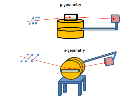
Reflectivity setup at Indus-1 beamline BL-4 was originally designed to measure reflectivity of linearly polarized SR beam which falls on sample surface with electric filed vector parallel to the surface (this is called s-polarization geometry). In this geometry the SR beams gets reflected in a vertical plane. This geometry was in use since last many years. For in-house research program and to cater the Indus users it was planned to modify the reflectivity setup for p-polarization geometry where the SR beam will fall on a sample surface with electric field vector perpendicular to it. In this geometry the beam will get reflected in the horizontal plane. A suitable platform has been fabricated and necessary modifications has been carried out in the experimental station. The modified setup has been installed. The new setup will be useful for many research problems. The molecular orientation in complex organic thin film can be measured by analyzing the difference in reflectivity of s and p geometry. Apart from this the p-geometry finds application for plasmonic excitation study in soft x-ray/VUV region which strongly depends on electric field vector of incident beam. The p-geometry is also useful for in-house multilayer research program where the polarization characteristics of the multilayer can be determined.
|
|
|
|
Schematic of s and p polarization setup for reflectivity measurements at Indus-1 reflectivty beamline.
|
|