|
Indus-1 Beamlines
|
|
PASS Beamline
|
Introduction
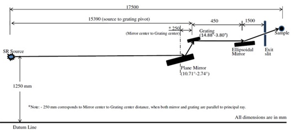
The PASS beamline will be used to measure the absorption spectra of solid samples of low Z (C, N, O, Ti, V) material both in thin film as well as bulk form. The beamline is indigenous developed and cover the energy range of 55eV to 840 eV. The absorption spectra both in XANES (X-ray Absorption Near Edge Structure) and EXAFS (Extended X-ray Absorption Fine Structure) mode of low Z-materials can be measured. Currently we are using total electron yield (TEY) mode of XAFS. The Schematic of the PASS beamline is given in Fig.1.
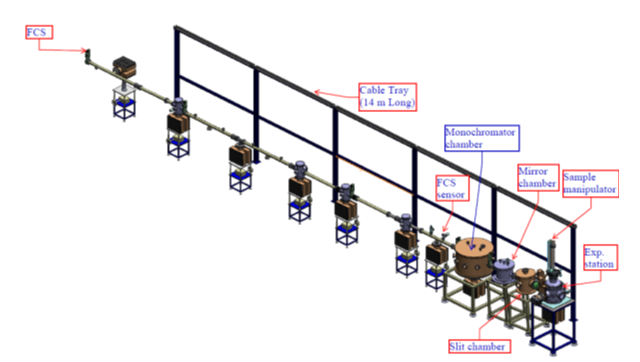
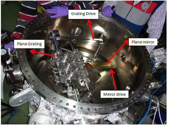
The complete beamline is maintained in ultra-high vacuum (UHV) environment. The major components of the beamline (Fig. 2, 3 and 4) include a SX-700 type plane grating monochromator (PGM) based having plane mirror and plane grating. The energy range of the beamline is covered by rotation of grating and simultaneously rotation as well as translation of the plane mirror using high precision motorized drives. The pivot of the grating is lying on the surface of grating and pivot of the mirror is lying outside the mirror surface. The next major component is ellipsoidal mirror to focus the beam at the slit in both meridional and sagittal plane.
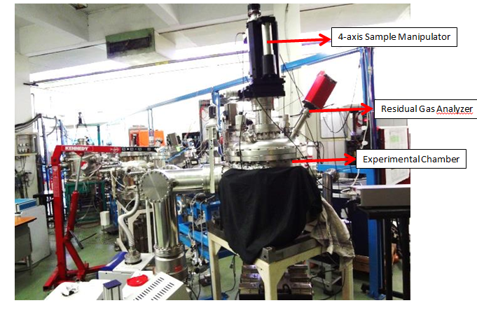
The experimental station of the beamline consists of 4-axis motion sample manipulator, sample holder facilitated with sample current measurement (I s), Ni mesh for initial current measurement (I 0),
The sample current I sis given by
Is = I0 exp(-μt)
Where μ absorption coefficient of material, t is the thickness upto the layer from which the electrons are coming out.
|
Fig.1: Schematic of the PASS beamline |
Beamline Specifications:
| Source |
Bending magnet BM02 |
| Length of the beamline |
17.5 mtrs from the tangent point |
| Energy Range |
55 eV – 840 eV |
| Acceptance of the beam |
2.6 mrad (H) X 0.25 mrad (V) |
| Monochromator |
SX-700 type PGM |
| No. of Grating |
1 (groove density : 1198 l/mm) |
| Energy Resolution (ΔE/E) |
~10-3 |
| Flux (at the sample) |
109 ph/s |
|
Fig.2: 3D view of PASS beamline |
|
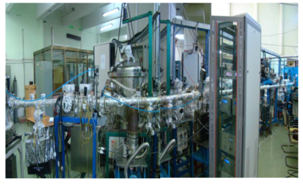
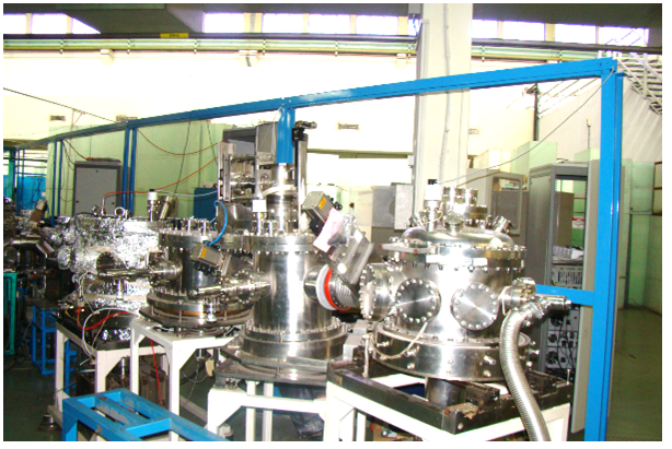
Fig.4: Major components of PASS beamline |
|
Fig.5: Inside view of in-house developed Plane Grating Monochromator |
|
Fig. 6: Experimental station of PASS beamline |
Result
|
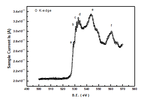
Fig.7: Oxygen K-edge of ZnO where a, b, c and d are pre-edge peaks due to different hybridized levels |
|
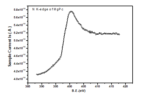
Fig.8: Nitrogen K-edge of Magnesium Pthalocynine (MgPc) film |
|
Fig.9: Carbon K-edge of MgPc peaks a and b corresponds to 1s- 𝜋* and 1s- 𝜎*transition. |
Present Status
The trial experiments on several samples have been performed
Contact Number: 91-731- 244- 8114/2118
In-charge:
Dr. R. K. Sharma Email: sharmark@rrcat.gov.in
Other contributers:
| Dr. Jagannath |
ssai@barc.gov.in |
Technical Physics Division
Bhabha Atomic Research Centre,
Mumbai – 400 085.
|
| Shri Jaspreet Singh |
jaspreet@rrcat.gov.in |
|
| Shri Uday Sule |
usule@rrcat.gov.in |
|
| Shri Pradeep R |
jpradeepr@barc.gov.in |
|
Last Updated on: September 2020
|
|